Yunxi Gloria-M Series Motor Communication Protocol
Feedback Frame
The feedback frame ID is set by the debugging assistant (Master ID), with a default of 0. It mainly feeds back the motor's position, speed, and torque information. Its frame format is defined as:
| Feedback Message | D[0] | D[1] | D[2] | D[3] | D[4] | D[5] | D[6] | D[7] |
|---|---|---|---|---|---|---|---|---|
| MST_ID | ID|ERR<<4 | POS[15:8] | POS[7:0] | VEL[11:4] | VEL[3:0]|T[11:8] | T[7:0] | T_MOS | T_Rotor |
Where:
- ID indicates the controller's ID, taken from the lower 8 bits of CAN_ID
- ERR indicates the status, corresponding to the following status types:
- 0 — Disabled
- 1 — Enabled
- 8 — Overvoltage
- 9 — Undervoltage
- A — Overcurrent
- B — MOS overtemperature
- C — Motor coil overtemperature
- D — Communication loss
- E — Overload
- POS indicates the motor's position information
- VEL indicates the motor's speed information
- T indicates the motor's torque information
- T_MOS indicates the average temperature of the MOS on the driver, in °C
- T_Rotor indicates the average temperature of the motor's internal coil, in °C
Position, speed, and torque use a linear mapping relationship to convert floating-point data types into signed fixed-point data, where position uses 16-bit data and both speed and torque use 12-bit. Speed is used as an example to illustrate the mapping relationship.
For example, if the current motor speed is 25.0 rad/s and the set speed range VMAX = 45 rad/s, the data message sent is:
Maximum Speed
The maximum speed is limited by various factors, including the supply voltage (V_BUS), the KV value, and the gear ratio (GR). An upper limit can usually be calculated using the following formula:
where is the number of pole pairs and represents the rotor flux linkage.
MIT Mode
MIT mode is compatible with the original MIT control protocol, achieving flexible impedance control through a weighted combination of three dimensions: position, speed, and torque. Users can freely set the control range (P_MAX maximum position, V_MAX maximum speed, T_MAX maximum torque), and the driver converts the CAN data into control variables and, after computation, outputs the torque current set value. Its control block diagram is shown below:
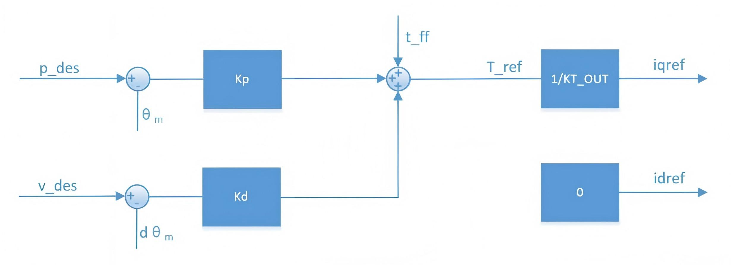
Figure caption: p_des — position command; v_des — speed command; t_ff — feedforward torque command; θ_m — actual motor position (feedback); dθ_m — actual motor speed (feedback); kp — position proportional coefficient; kd — position derivative coefficient; T_ref — torque reference value; 1/KT_OUT — reciprocal of the torque coefficient (converts torque to current); iqref — q-axis current command; idref — d-axis current command (always 0).
Various control modes can be derived from MIT mode. For example, when kp=0 and kd is non-zero, setting v_des achieves constant-speed rotation; when kp=0 and kd=0, setting t_ff achieves a given torque output.
When controlling position, kd must not be set to 0, otherwise it will cause the motor to oscillate or even lose control.
Control Frame in MIT Mode
| Control Message | D[0] | D[1] | D[2] | D[3] | D[4] | D[5] | D[6] | D[7] |
|---|---|---|---|---|---|---|---|---|
| ID | p_des[15:8] | p_des[7:0] | v_des[11:4] | v_des[3:0]|Kp[11:8] | Kp[7:0] | Kd[11:4] | Kd[3:0]|t_ff[11:8] | t_ff[7:0] |
- The frame ID equals the set CAN ID value
- P_des: position command
- V_des: speed command
- Kp: position proportional coefficient
- Kd: position derivative coefficient
- T_ff: torque command value
Each parameter conforms to the mapping relationship in the previous section, where the ranges of p_des, v_des, and t_ff can be set by the debugging assistant, the range of Kp is [0, 500], and the range of Kd is [0, 5].
A standard CAN data frame has only 8 bytes. The MIT control command format combines the five parameters Position, Velocity, Kp, Kd, and Torque bitwise into the 8 bytes, where Position occupies 16 bits, and Velocity, Kp, Kd, and Torque each occupy 12 bits, for a total of 64 bits (8 bytes).
Position-Velocity Mode
Position-velocity mode uses a three-loop cascade control of position loop → speed loop → current loop, achieving smooth and precise positional motion by specifying a target position and maximum speed. It is suitable for scenarios that require trajectory precision and compliance. Its control block diagram is shown below:
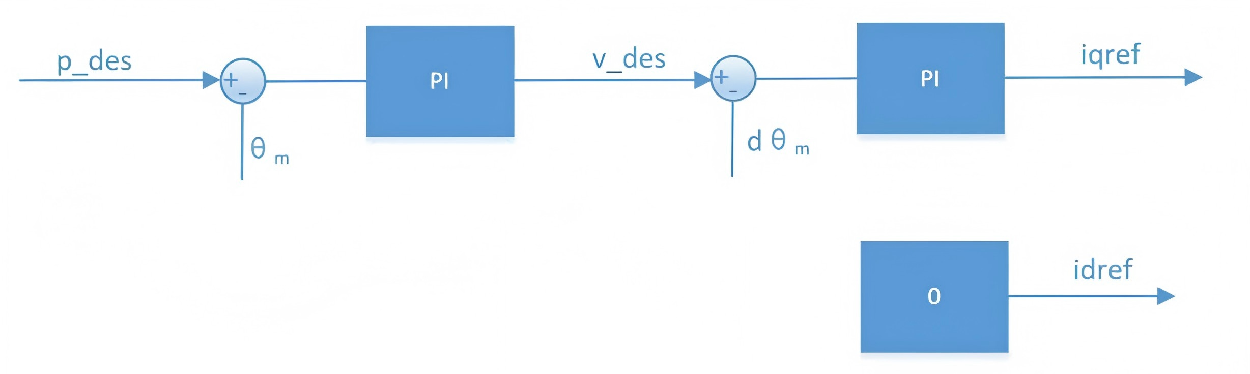
Figure caption: p_des — target position command; v_des — speed command (limits the maximum absolute speed); θ_m — actual motor position (feedback); dθ_m — actual motor speed (feedback); PI — PI controller; iqref — q-axis current command; idref — d-axis current command (always 0).
- p_des is the target position for control, and v_des is used to limit the maximum absolute speed during motion
- Using the control parameters recommended by the debugging assistant yields good control precision; the process is relatively compliant but the response time is longer. In addition to v_des, the configurable parameters also include acceleration and deceleration; if additional oscillation occurs during control, the acceleration/deceleration values can be appropriately increased
The units of p_des and v_des are rad and rad/s respectively, and their data type is float. The damping factor must be set to a non-zero positive number; refer to the notes for speed mode.
Control Frame in Position-Velocity Mode
| Control Message | D[0] ~ D[3] | D[4] ~ D[7] |
|---|---|---|
| 0x100+ID | p_des (float, little-endian) | v_des (float, little-endian) |
- The frame ID is the set CAN ID value plus an offset of 0x100
- P_des: position command, floating-point, low byte first, high byte last
- V_des: speed command, floating-point, low byte first, high byte last
Here the CAN ID for sending the command is 0x100+ID, and the speed command is the speed of the constant-velocity segment during trapezoidal acceleration/deceleration.
Enable
After power-on self-check is complete, an "Enable" command must be sent before control is possible. The "Enable" frame is a control frame, with the frame ID as described above. The difference is the data segment; regardless of the mode, the data segment definition for "Enable" is the same, as follows:
| D[0] | D[1] | D[2] | D[3] | D[4] | D[5] | D[6] | D[7] |
|---|---|---|---|---|---|---|---|
| 0xFF | 0xFF | 0xFF | 0xFF | 0xFF | 0xFF | 0xFF | 0xFC |
Disable
Disable is the default state of the motor at power-on. In this state, the motor's three-phase terminal voltage waveforms are identical, all being a 50% modulation wave of the supply voltage. The "Disable" frame is a control frame, with the frame ID as described above, and the data segment defined as follows:
| D[0] | D[1] | D[2] | D[3] | D[4] | D[5] | D[6] | D[7] |
|---|---|---|---|---|---|---|---|
| 0xFF | 0xFF | 0xFF | 0xFF | 0xFF | 0xFF | 0xFF | 0xFD |
Save Position Zero Point
The "Save Position Zero Point" frame is a control frame, with the frame ID as described above, and the data segment defined as follows:
| D[0] | D[1] | D[2] | D[3] | D[4] | D[5] | D[6] | D[7] |
|---|---|---|---|---|---|---|---|
| 0xFF | 0xFF | 0xFF | 0xFF | 0xFF | 0xFF | 0xFF | 0xFE |
Clear Error
When the motor experiences an error such as overheating, sending a "Clear" command can clear the error. The "Clear" frame is a control frame, with the frame ID as described above, and the data segment defined as follows:
| D[0] | D[1] | D[2] | D[3] | D[4] | D[5] | D[6] | D[7] |
|---|---|---|---|---|---|---|---|
| 0xFF | 0xFF | 0xFF | 0xFF | 0xFF | 0xFF | 0xFF | 0xFB |
Motor Register Operations
Read Command Format
| Message ID | Attribute | data[0] | data[1] | data[2] | data[3] |
|---|---|---|---|---|---|
| 0x7FF | STD | CAND_L | CAND_H | 0x33 | RID |
After a successful read, the data of that register is returned. The frame format is as follows:
| Message ID | Attribute | data[0] | data[1] | data[2] | data[3] | data[4] | data[5] | data[6] | data[7] |
|---|---|---|---|---|---|---|---|---|---|
| MST_ID | STD | CAND_L | CAND_H | 0x33 | RID | Data 0 | Data 1 | Data 2 | Data 3 |
The returned data is low byte first, high byte last.
Write Command Format
| Message ID | Attribute | data[0] | data[1] | data[2] | data[3] | data[4] | data[5] | data[6] | data[7] |
|---|---|---|---|---|---|---|---|---|---|
| 0x7FF | STD | CAND_L | CAND_H | 0x55 | RID | Data 0 | Data 1 | Data 2 | Data 3 |
After a successful write, the written data is returned, with the same frame format as sent:
| Message ID | Attribute | data[0] | data[1] | data[2] | data[3] | data[4] | data[5] | data[6] | data[7] |
|---|---|---|---|---|---|---|---|---|---|
| MST_ID | STD | CAND_L | CAND_H | 0x55 | RID | Data 0 | Data 1 | Data 2 | Data 3 |
The data is low byte first, high byte last.
Store Command Format
| Message ID | Attribute | data[0] | data[1] | data[2] | data[3] |
|---|---|---|---|---|---|
| 0x7FF | STD | CAND_L | CAND_H | 0xAA | RID |
After a successful store, the return format is:
| Message ID | Attribute | data[0] | data[1] | data[2] | data[3] |
|---|---|---|---|---|---|
| MST_ID | STD | CAND_L | CAND_H | 0xAA | 0x01 |
Register Table
RID is the register. For detailed register entries, refer to the control protocol document. Only one register variable is listed here as an example:
| Register Address | Variable | Description | R/W | Range | Data Type |
|---|---|---|---|---|---|
| 10 (0x0A) | CTRL_MODE | Control mode | RW | [1, 4] | uint32_t |
Parameter Description
Motor Parameters
| Parameter | Description |
|---|---|
| Phase Resistance (R) | The resistance value between phases, in mΩ |
| Phase Inductance (L) | The inductance value between phases, in μH |
| Flux Linkage (λ) | The flux linkage value of the permanent magnet field, in Wb |
| Viscous Coefficient | The motor's viscous coefficient, for reference only, not used, in N·m·s/rad |
| Moment of Inertia | The motor's moment of inertia; keep it as no-load as possible during identification, in kg·m² |
Driver Parameters
| Parameter | Description |
|---|---|
| Pole Pairs | The number of pole pairs of the motor rotor; can be written manually or automatically calculated through calibration |
| Gear Ratio | The reduction ratio of the external gear, indicating how much reduction the motor undergoes for output |
| CAN ID | The motor identification ID used for CAN communication; the final transmission uses the message format mode plus an offset value |
| Master ID | The CAN StdID used by the motor for CAN communication |
| Undervoltage | Undervoltage protection threshold, in V |
| Overvoltage | Overvoltage protection threshold, in V |
| Overtemperature | Motor overtemperature protection threshold, in °C |
| CAN Timeout | CAN communication timeout period setting, measured in units of 50 μs |
| Acceleration | The motor acceleration set value, in Krad/s² |
| Deceleration | The motor deceleration setting, in Krad/s²; keep it as consistent as possible with the acceleration value |
| Speed Limit | The theoretical maximum speed of the motor, a system-calculated value; if there is a gearbox, this value is the value before reduction, in rad/s |
| Overcurrent | The overcurrent threshold percentage of the motor phase current peak |
Control Amplitudes
| Parameter | Description |
|---|---|
| PMAX | The maximum position value for sending commands in MIT mode, and the maximum value used for position feedback in all modes, in rad |
| VMAX | The maximum speed value for sending commands in MIT mode, and the maximum value used for speed feedback in all modes, in rad/s |
| TMAX | The maximum torque value for sending commands in MIT mode, and the maximum value used for torque feedback in all modes, in Nm |
| KT_OUT | The output torque coefficient value used by the driver board; if 0.0 is used, the system's theoretical calculated value is used by default, in Nm/A |
| Gear Coefficient | The gear torque transmission efficiency value, default is 1 |
| Damping Factor | The speed-loop damping factor set value, default 4.0, recommended range 2.5~20. Too small causes overshoot; too large affects rise time |
Control Settings
| Parameter | Description |
|---|---|
| Control Mode | Includes 3 modes: MIT mode, position-velocity mode (PV), and pure speed mode |
| Current Bandwidth | The control bandwidth of the current loop, adjusted according to actual needs |
| Speed KP | The proportional parameter of the speed loop; can be set manually, and after setting, click write parameter to save permanently |
| Speed KI | The integral coefficient of the speed loop; can be set manually, and after setting, click write parameter to save permanently |
| Position KP | The proportional parameter of the position loop, effective in position-velocity mode; click "Calculate KP" to compute automatically |
| Position KI | The integral coefficient of the position loop, recommended to be set to 0.0 |